Project Brief
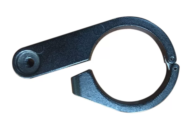
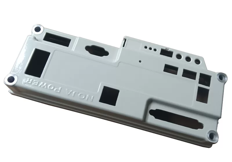
Seatpost Clamp Lever, a custom-made bicycle component crafted from die-cast aluminum alloy, is a critical part of the bicycle that requires precision assembly.
1. Product Standards & Requirements: Material: K-ALLoy; General dimensional tolerance grade: ISO 8062-CT3, Minimum tolerance: ±0.1; Flawless appearance (no visible defects); Surface roughness: Ra6.3µm; Exterior: black fine texture powder coating, thickness 100±20µm; Neutral salt spray test: 240 hours. PPAP approval must be completed and passed before formal mass production.
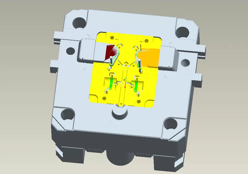
2. Product Challenges: The product has an unconventional, unique structure, posing difficulties in mold design. High appearance requirements involve both A-side and B-side surfaces.
This Seatpost Clamp Lever casting not only boasts exceptional machining precision and surface finish but also exhibits outstanding thermal conductivity, corrosion resistance, lightweight properties, and convenient installation and maintenance capabilities. The final product fully meets the customer's design objectives, providing a higher-performance, more reliable solution for this category of components.
Production Process
Mould making→Melting→High Pressure Die Casting→Cutting the sprue and riser→Deburring→Shot Blasting→Machinine 1→Machinine 2→Machinine 2→Clean→Packaging & inspection
FAQs
Q1. What mechanical demands does a seatpost clamp lever face in use?
The lever is a hand-operated quick-release mechanism that riders engage and disengage repeatedly, often under load. It must generate sufficient clamping force to secure the seatpost, withstand bending stress at the pivot bore during each operation, and maintain its geometry across thousands of cycles without fatigue cracking—all within a part weighing only 33g and 10mm thick.
Q2. Why does a 10mm-thin lever with 2.5mm minimum wall present specific die casting challenges?
At only 10mm deep, metal must flow laterally across a large plan area before solidifying—thin sections freeze rapidly, increasing cold shut and short shot risk at the lever extremities. The unconventional shape creates complex flow patterns requiring precise gate positioning and injection speed control to fill all features without defects on either the A-side or B-side appearance surfaces.
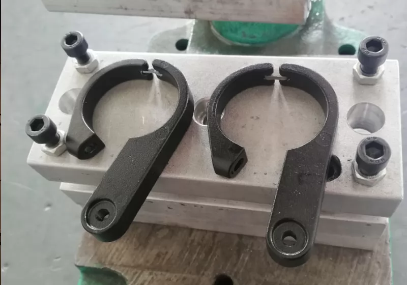
Q3. Why does this small lever require three CNC machining operations?
The lever has functional features in multiple orientations—pivot bore, clamping interface, and profile surfaces—that cannot all be accessed from one fixturing direction. Three sequential operations allow each feature group to be machined from its optimal approach angle, maintaining ±0.1mm tolerance across all critical interfaces and ensuring the pivot bore is accurately positioned for correct mechanical action.
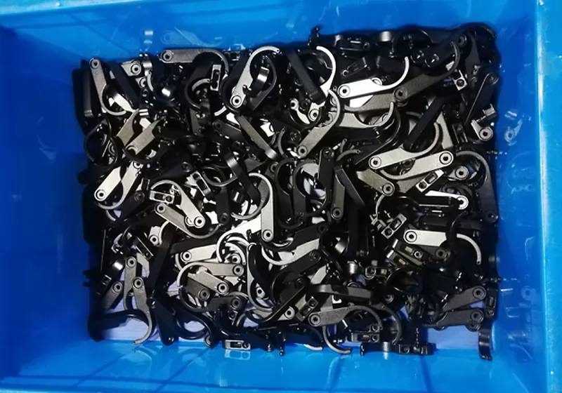
Q4. Why does the fine texture powder coating on this lever have a strict thickness of 100±20µm?
On a part only 10mm thick, coating thickness variation is proportionally more significant than on larger parts. Excess buildup at pivot features or edges can interfere with lever travel and assembly fit, while insufficient thickness compromises grip feel and corrosion protection. The fine texture also improves hand grip during operation—making the specification functional, not merely aesthetic.
Q5. What unique structural challenges does the "unconventional shape" of this lever create for mold design?
A seatpost clamp lever typically features asymmetric profiles, a cam or pivot geometry, and functional openings at non-standard angles—none of which align neatly with a standard two-part mold opening direction. This forces the use of angled sliders or lifters to form undercut features, and their precise alignment directly determines parting line quality on the appearance surfaces. Any slider misalignment produces visible steps or flash on a part where both faces are consumer-visible.
Share your thoughts
Showing
6
of
0
reviews