Project Brief
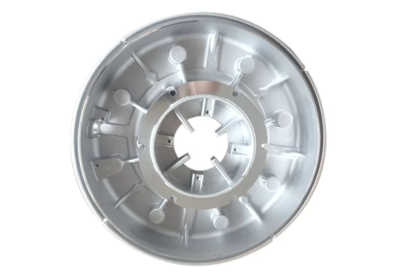
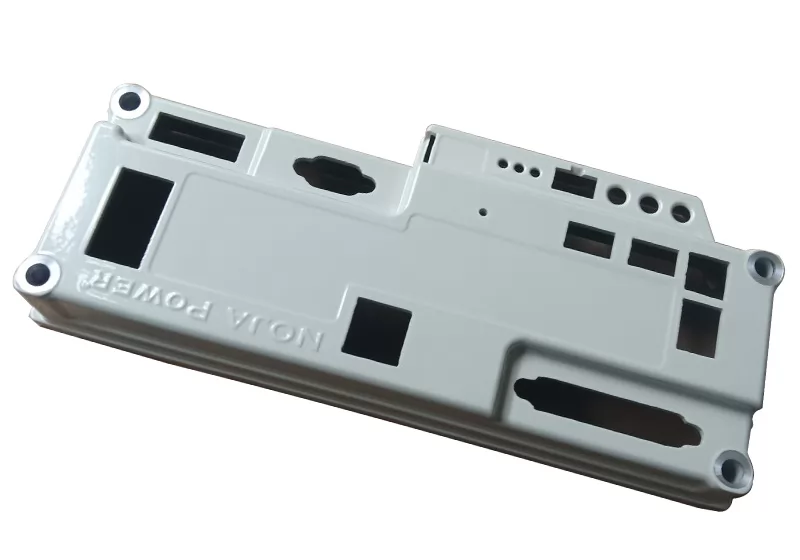
This is an aluminum casting for a motor end cover, a core component of the motor. The motor end cover not only protects internal components but also serves multiple functions including thermal management and mechanical support.
1. Product Standards & Requirements: Material ADC12; Full-dimension tolerance grade ISO 8062-CT3, critical dimension tolerances as tight as ±0.01mm; No visible surface defects, surface roughness Ra 0.8µm, porosity standards per ISO 10049; PPAP approval must be completed and passed prior to formal mass production.
2. Product Challenges: Wall thickness ranges from 4mm to 9mm, prone to porosity issues. Structural die casting risks material shorting, with intermediate flash areas susceptible to thickening. Surface finish demands exceptional smoothness, assembly precision is highly critical, and CNC machining requirements are demanding.
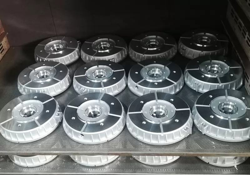
The finished product must not only exhibit excellent machining precision and surface finish but also deliver superior thermal conductivity, corrosion resistance, lightweight characteristics, and ease of installation and maintenance. The final product fully meets the customer's design objectives, providing a higher-performance and more reliable solution for this type of component design.
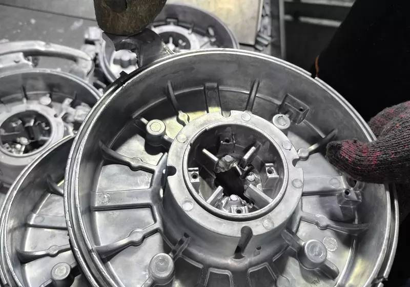
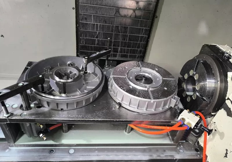
Production Process
Mould making→Melting→High Pressure Die Casting→Cutting the sprue and riser→Deburring→Shot Blasting→Machinine 1→Machinine 2→Machinine 2→Clean→Packaging & inspection
FAQs
Q1. What structural and functional role does this end cover play in an industrial automation motor?
The end cover closes and seals one end of the motor housing, providing the bearing seat that supports and locates the rotor shaft. It simultaneously protects the internal stator and winding assembly, conducts heat away from the motor body, and serves as a structural mounting face for assembly integration. In industrial automation systems, any dimensional deviation in the bearing seat directly affects rotor concentricity and motor vibration performance, which is why critical tolerances reach ±0.01mm.
Q2. Why does the 4–9mm wall thickness variation on this end cover create porosity risk?
In HPDC, thick and thin sections solidify at different rates. Where thick sections (up to 9mm) adjoin thinner walls (4.5mm minimum), the thick zones remain molten longer and cannot be fed adequately as they shrink—creating shrinkage porosity. On a large end cover (2860g, nearly 300mm across), these thermal gradients are amplified, making porosity control more demanding than on smaller or more uniform-wall parts. Internal quality is verified against ISO 10049 porosity standards.
Q3. Why does this end cover require Ra 0.8µm surface roughness, and on which surfaces?
Ra 0.8µm is required on the bearing seat bore and the mating flange face—surfaces that interface with precision bearings and the motor housing respectively. The bearing seat must be smooth enough to achieve a controlled interference or clearance fit without surface asperities causing uneven stress on the bearing ring, while the flange face requires this finish to ensure proper sealing and flatness at the motor assembly joint. These surfaces are finish-machined in the final CNC operations.
Q4. What makes achieving ±0.01mm tolerance on a 288 × 299mm die casting particularly demanding?
At this size, thermal expansion of the aluminum workpiece during machining becomes a significant source of dimensional drift—a 1°C temperature change on a ~300mm aluminum part can shift dimensions by several microns. Combined with the inherent dimensional variation of a 2860g HPDC blank, holding ±0.01mm requires machining in a temperature-controlled environment, careful datum selection, and a multi-stage CNC strategy that progressively removes stock and allows the part to stabilize between operations.
Q5. Why does this end cover use ISO 8062-CT3 as its casting tolerance grade rather than the more common ISO 2768?
ISO 8062 is the international standard specifically for casting dimensional tolerances, with CT3 representing one of the tightest grades applicable to die castings. It defines allowable dimensional variation directly on the as-cast blank—before CNC machining—which matters because tighter blank accuracy means less stock removal, better datum stability, and reduced risk of machining through the surface layer into porous subsurface zones. ISO 2768 by contrast governs general machined part tolerances and is applied after machining; both standards are used together on this part.
Share your thoughts
Showing
6
of
0
reviews