Die Casting Tolerances: Standards, Types, and What to Expect from Aluminum
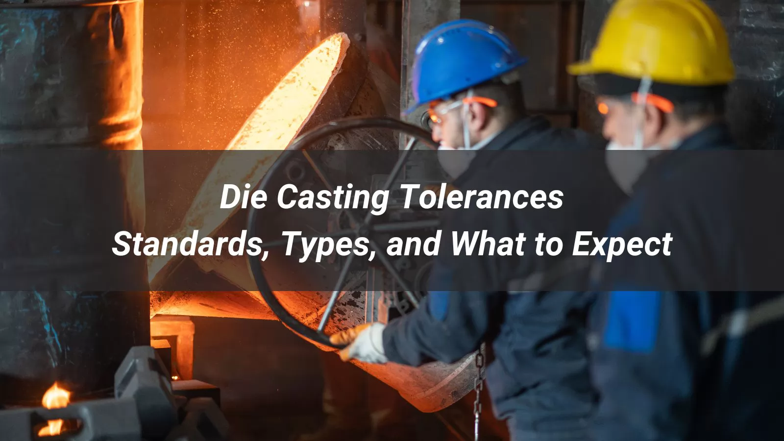
In high-volume metal manufacturing, controlling die casting tolerances is often the difference between a part that assembles first time and one that generates costly rework. As industries from automotive to medical equipment push for lighter, more complex components, the dimensional precision demanded from cast parts has never been higher — and the margin for error has never been smaller.
This guide addresses the questions engineers and procurement teams face most often when specifying or sourcing die cast components:
- What tolerance ranges are realistically achievable with aluminum, zinc, and magnesium die casting?
- Which industry standards — NADCA, ISO 8062-3 — apply, and how do they differ?
- What factors drive dimensional variation, and how can they be controlled?
- When does a casting need secondary machining to meet tighter requirements?
- How should tolerance levels be selected to balance precision with production cost?
From tolerance types and international standards to aluminum-specific data and inspection methods, this guide covers the core concepts that shape dimensional quality in die casting — because choosing the right tolerance strategy from the start is one of the most effective ways to reduce cost, avoid rework, and get production right the first time. Read on to find out what to specify, what to expect, and where the real trade-offs lie.
Table of Contents
- What Are Die Casting Tolerances, and Why Do They Matter?
- Industry Standards That Govern Casting Tolerances
- Types of Tolerances in Die Casting
- Aluminum Die Casting Tolerances in Practice
- How Tight Can Pressure Die Casting Tolerances Get?
- What Factors Affect Dimensional Accuracy in Die Casting?
- Common Challenges in Maintaining Tight Tolerances
- How Are Die Cast Parts Inspected for Tolerance Compliance?
- Choosing the Right Tolerance Level for Your Project
- FAQ
What Are Die Casting Tolerances, and Why Do They Matter?
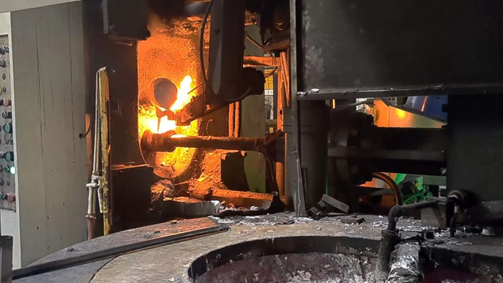
In die casting, perfection on paper rarely survives contact with molten metal. Every part you produce will deviate — slightly — from its intended dimensions. Tolerances define how much deviation is acceptable before a part fails to fit, function, or meet quality requirements.
The Basic Definition
A die casting tolerance is the permissible range of variation between a part's actual measured dimension and its nominal (design) dimension. It is typically expressed as a bilateral range — for example, ±0.10 mm — meaning the actual measurement can be 0.10 mm above or below the target and still be considered acceptable.
A simple example: If a housing component is designed with a length of 100 mm and assigned a tolerance of ±0.15 mm, any finished part measuring between 99.85 mm and 100.15 mm passes inspection. Outside that window, the part is rejected or reworked.
Tolerances apply to every measurable feature of a casting — length, width, hole diameter, flatness, angularity, and more. They are not a single number but a system of limits that together define whether a part is usable.
Why Variation Is Unavoidable
Die casting involves forcing molten metal into a steel mold under high pressure, then allowing it to cool and solidify. Each stage introduces potential dimensional change. The table below outlines where variation typically enters the process:
| Stage | Source of Variation | Typical Effect |
|---|---|---|
| Filling | Injection speed and pressure fluctuation | Incomplete fill, flash, or dimensional shift |
| Solidification | Uneven cooling across the part | Warping, shrinkage, internal stress |
| Ejection | Mechanical force during part removal | Minor distortion, surface marking |
| Post-cooling | Continued thermal contraction at room temperature | Slight dimensional change from die measurement |
These variations are inherent to the process. The role of tolerances is to quantify and manage them — not eliminate them entirely.
Why Tolerances Matter
Setting the right tolerances has a direct impact on fit, function, and cost. Most die cast parts are assembled with other components — housings, seals, shafts, or fasteners. If dimensions fall outside tolerance, parts may not assemble correctly, seals may leak, or mechanical loads may distribute unevenly.
In automotive applications, an engine housing with insufficient dimensional control can lead to vibration, oil leakage, or premature wear — failures that are costly to trace back to a casting issue after final assembly.
Tolerances also shape manufacturing cost. Tighter limits require more precise tooling, stricter process control, and often secondary machining. Defining them appropriately — tight where it matters, relaxed where it doesn't — is one of the most effective ways to keep production cost in check without compromising quality.
Who Defines the Limits?
Die casting tolerances draw from industry standards, material data, and application requirements — often in combination. In North America, NADCA publishes the most widely referenced guidelines, with separate tables for aluminum, zinc, and magnesium alloys. Internationally, ISO 8062-3 provides a graded system used across global supply chains.
Note: Customer specifications may impose tighter limits than standard industry tables allow. Tolerance requirements should always be aligned between designer, buyer, and manufacturer before tooling is committed.
Industry Standards That Govern Casting Tolerances
Tolerance limits in die casting are not left to guesswork. Two major frameworks — one North American, one international — provide the reference points that manufacturers, buyers, and engineers rely on when specifying and validating dimensional requirements.
NADCA Guidelines for Die Casting
The North American Die Casting Association (NADCA) publishes the most widely used tolerance standards for pressure die casting in North America. These guidelines cover aluminum, zinc, and magnesium alloys and are organized into two tiers:
| Tier | Description | Typical Use Case |
|---|---|---|
| Standard Tolerances | Achievable under normal production conditions without special tooling or process adjustments | Enclosures, brackets, general structural parts |
| Precision Tolerances | Require tighter die construction, closer process control, and sometimes secondary machining | Engine components, optical housings, critical assemblies |
NADCA tolerance values are dimension-dependent — the larger the feature, the wider the allowable variation. This reflects the physical reality that larger castings accumulate more shrinkage and thermal variation during cooling. You can find the official NADCA product standards at the NADCA official website.
ISO 8062-3 and DCTG Grade Classification
Internationally, ISO 8062-3 defines casting tolerances through a graded system known as DCTG (Dimensional Casting Tolerance Grade). Grades run from DCTG 1 (tightest) to DCTG 16 (loosest), giving engineers a universal language for specifying dimensional expectations regardless of geography or supplier. The full standard is published by the International Organization for Standardization (ISO).
High-pressure die castings — including most aluminum and zinc parts — typically fall within DCTG 4 to DCTG 6 without secondary machining. Sand castings, by comparison, usually achieve DCTG 11 to DCTG 13 at best.
Using ISO 8062-3 grades simplifies communication across global supply chains, allowing a designer in Germany and a supplier in China to reference the same dimensional expectations without ambiguity.
Standard Tolerances vs. Precision Tolerances: How to Choose
The decision between standard and precision tolerances involves balancing functional requirements against cost. Neither is universally better — the right choice depends on what the part needs to do.
| Factor | Standard Tolerances | Precision Tolerances |
|---|---|---|
| Tooling cost | Lower | Higher |
| Process control required | Moderate | Stringent |
| Secondary machining | Rarely needed | Often required |
| Lead time impact | Minimal | Moderate to significant |
| Best suited for | Non-critical fits, high-volume parts | Bearing seats, sealing surfaces, critical assemblies |
A practical approach is to apply precision tolerances only to features where fit or function genuinely requires it, and allow standard tolerances everywhere else. Over-specifying tight tolerances across an entire part is one of the most common — and avoidable — sources of unnecessary cost in die casting projects.
Types of Tolerances in Die Casting
Die casting tolerances are not one-size-fits-all. Different features of a part require different types of tolerance control, each addressing a specific kind of dimensional variation that can arise during the casting process.
1. Linear Tolerances
Linear tolerances govern straight-line dimensions — length, width, height, and feature spacing. They are the most commonly referenced type and form the baseline for most casting specifications.
For aluminum die casting, standard linear tolerances typically start at ±0.10 mm for small features, with values increasing proportionally as part dimensions grow. A general rule of thumb: expect roughly ±0.05 mm per 25 mm of dimension under standard production conditions.
Practical note: Linear tolerances are measured after the part has fully cooled to room temperature. Dimensional checks taken directly after ejection will not reflect the final part size.
2. Flatness and Geometric Tolerances
Where linear tolerances control size, geometric tolerances control shape, orientation, and position. Common geometric tolerances in die casting include:
| Type | What It Controls | Typical Minimum Value (Aluminum) |
|---|---|---|
| Flatness | Deviation of a surface from a perfect plane | ±0.025 mm (±0.001 in) |
| Straightness | Deviation along a linear axis | ±0.05 mm per 25 mm |
| Parallelism | Alignment between two opposing surfaces | ±0.05–0.10 mm |
| Angularity | Deviation from a specified angle | ±0.5° |
| Roundness | Circularity of holes or cylindrical features | ±0.03–0.08 mm |
Flatness is particularly important for sealing surfaces, mounting faces, and mating flanges. Even small deviations can cause leaks or uneven load distribution in assembled parts.
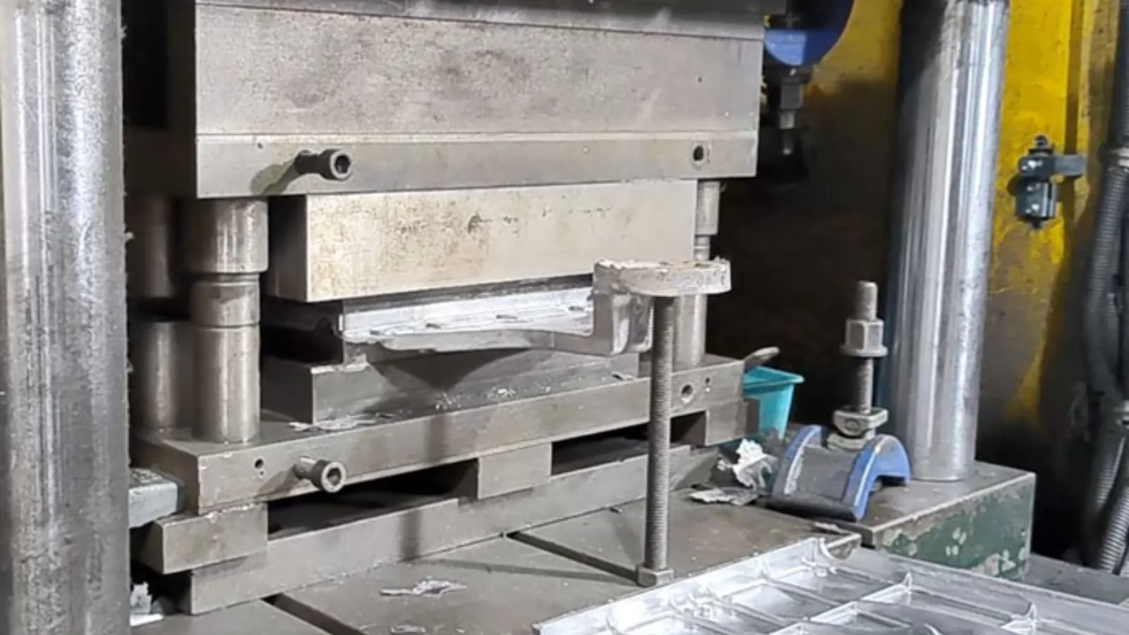
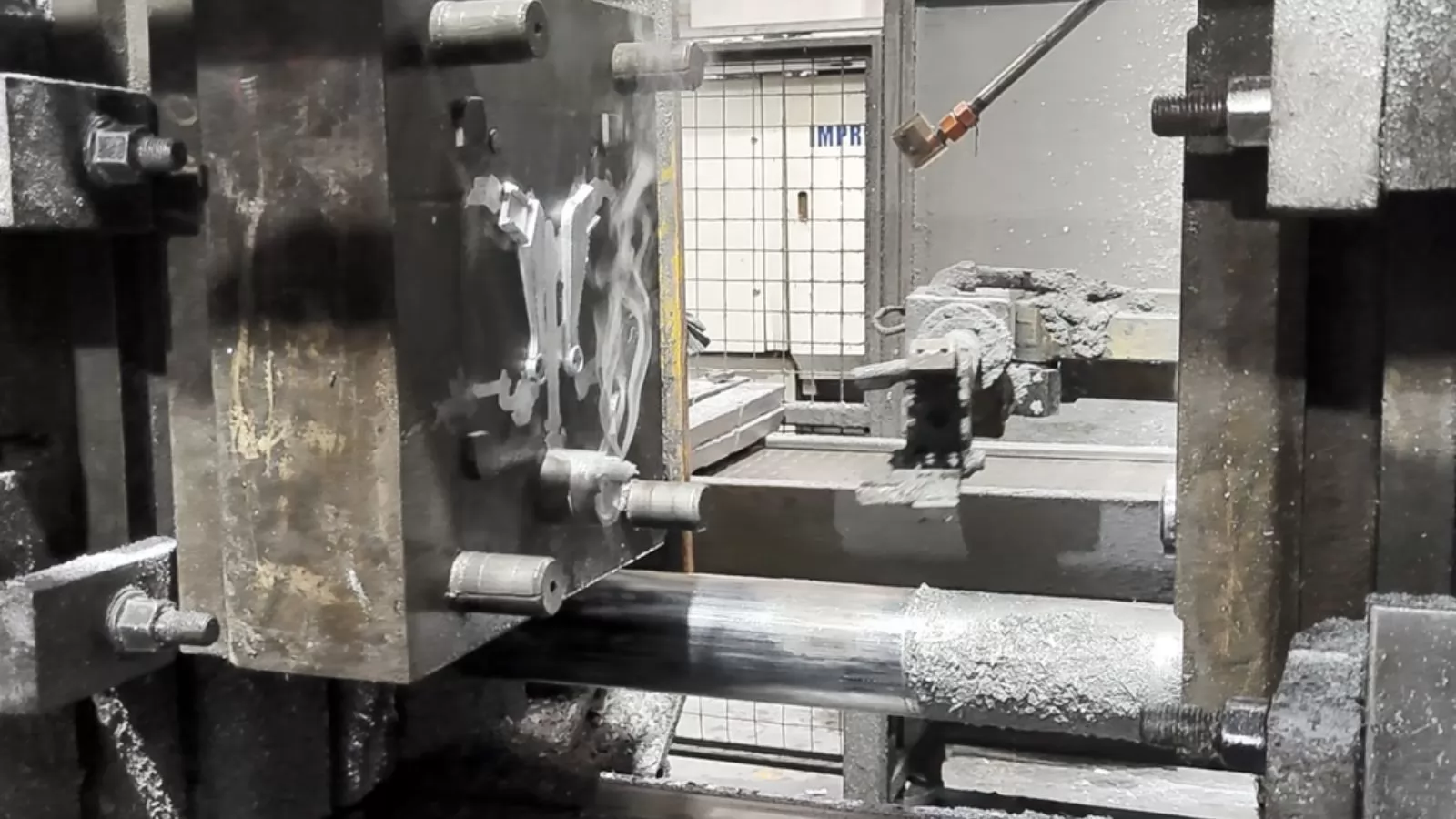
3. Parting Line Tolerances
The parting line is where the two halves of the die meet. Under injection pressure, a small amount of die separation is unavoidable — this is what produces flash. Parting line tolerances define the maximum allowable mismatch or flash thickness at this boundary.
For aluminum die casting, parting line tolerances typically range from ±0.10 mm to ±0.25 mm, depending on die quality, clamping force, and part geometry. On visible or cosmetic surfaces, tighter control is usually specified to avoid secondary deburring operations.
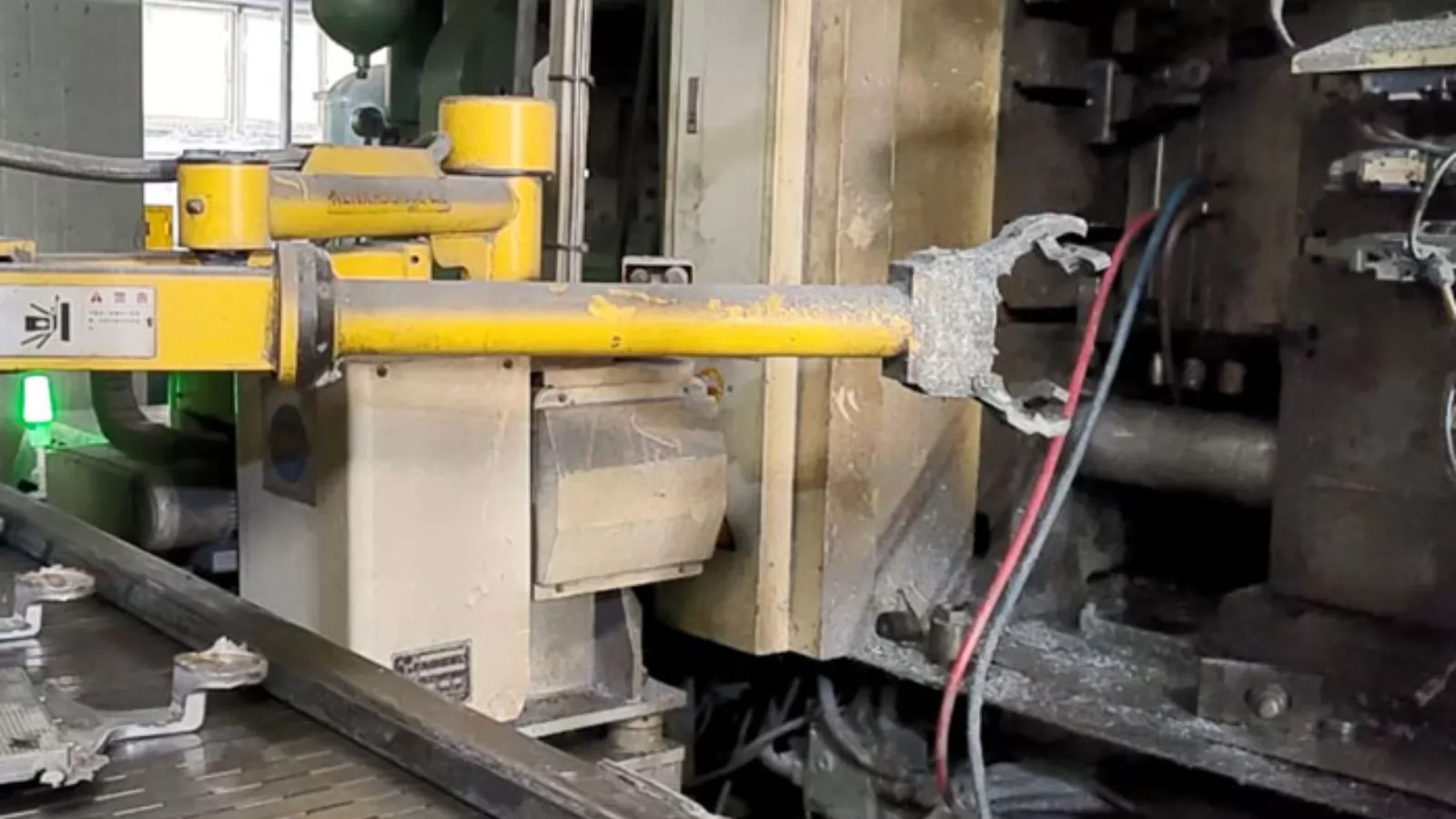
4. Moving Die Part Tolerances
Complex parts often require slides, cores, or inserts within the die to form undercuts, internal channels, or threaded features. These moving elements introduce an additional source of dimensional variation due to mechanical play, thermal expansion, and wear over time.
Tolerances for moving die components generally fall in the range of ±0.05 mm to ±0.15 mm. As die wear accumulates over production cycles, these values can drift — making regular tooling inspection an important part of long-term tolerance management.
Worth noting: Features formed by moving die parts — such as side holes or internal bosses — are typically held to slightly looser tolerances than features formed entirely within a single die half. This should be factored in during early design review.
Aluminum Die Casting Tolerances in Practice
Aluminum is the most widely used material in die casting, valued for its favorable strength-to-weight ratio, corrosion resistance, and good dimensional stability. Understanding the tolerance ranges realistically achievable with aluminum helps engineers design parts that can be produced efficiently without over-specifying precision.
Standard Tolerance Values for Aluminum
The following values represent typical aluminum die casting tolerances under standard production conditions, based on NADCA guidelines. These apply to parts produced in hardened steel dies using high-pressure die casting:
| Feature Type | Standard Tolerance (Aluminum) | Precision Tolerance (Aluminum) |
|---|---|---|
| Linear dimension (per 25 mm) | ±0.10 mm (±0.004 in) | ±0.05 mm (±0.002 in) |
| Minimum linear tolerance | ±0.13 mm (±0.005 in) | ±0.08 mm (±0.003 in) |
| Hole diameter | ±0.08 mm (±0.003 in) | ±0.05 mm (±0.002 in) |
| Flatness (per 25 mm) | ±0.10 mm (±0.004 in) | ±0.025 mm (±0.001 in) |
| Parting line shift | ±0.25 mm (±0.010 in) | ±0.10 mm (±0.004 in) |
| Moving die part features | ±0.15 mm (±0.006 in) | ±0.08 mm (±0.003 in) |
These figures serve as a planning baseline. Actual achievable tolerances depend on part size, wall thickness, alloy selection, and die condition — all of which should be discussed with your manufacturer before design is finalized.
How Aluminum Shrinkage Affects Tolerances
Aluminum contracts as it cools from liquid to solid state. The typical volumetric shrinkage rate for aluminum alloys used in die casting is approximately 1.0–1.3%. Dies are designed with this compensation built in, but uneven cooling across complex geometries can still cause localized dimensional variation.
Where shrinkage causes the most trouble: thick sections adjacent to thin walls, large flat areas without sufficient ribbing, and long unsupported spans. These are the regions most likely to warp or pull out of tolerance during cooling.
How Aluminum Compares to Zinc and Magnesium
Aluminum is not the tightest-tolerance option in die casting. Zinc die casting, with its lower melting point and more predictable shrinkage, consistently achieves tighter dimensional control. Magnesium sits between the two. The comparison below helps put aluminum's capabilities in context:
| Alloy | Typical Linear Tolerance (per 25 mm) | Relative Dimensional Stability | Common Applications |
|---|---|---|---|
| Zinc | ±0.038 mm (±0.0015 in) | Highest | Small precision components, connectors, gears |
| Aluminum | ±0.05–0.10 mm (±0.002–0.004 in) | Good | Automotive housings, structural frames, heat sinks |
| Magnesium | ±0.05–0.13 mm (±0.002–0.005 in) | Moderate | Lightweight enclosures, aerospace components |
For most structural and functional applications, aluminum die casting tolerances are more than sufficient. Where sub-±0.05 mm control is required across all features, zinc may be worth evaluating — or secondary CNC machining added to the aluminum process.
When Secondary Machining Is Needed
Die casting alone cannot always meet the tolerance demands of critical features such as bearing seats, precision bores, or threaded interfaces. In these cases, the casting is produced with intentional excess material (machining stock), then brought to final dimension by CNC milling, drilling, or reaming.
This two-stage approach — cast to shape, machine to tolerance — is standard practice in automotive and aerospace applications where certain features must hold ±0.02 mm or tighter. It allows the bulk of the part geometry to benefit from the speed and cost efficiency of die casting, while ensuring critical interfaces meet the precision requirements of the application.
How Tight Can Pressure Die Casting Tolerances Get?
One of the most common questions engineers ask when evaluating die casting for a new project is how precise the process can realistically be. The answer depends on several variables — but pressure die casting is capable of significantly tighter tolerances than most other casting methods, and in some cases can approach the lower boundary of what machining adds value to.
The Practical Tolerance Limits
Under well-controlled production conditions, high-pressure die casting can achieve the following dimensional limits without secondary machining:
| Condition | Achievable Linear Tolerance | Notes |
|---|---|---|
| Standard production (aluminum) | ±0.10–0.13 mm | Normal tooling, stable process |
| Precision production (aluminum) | ±0.05–0.08 mm | High-quality tooling, close process monitoring |
| Standard production (zinc) | ±0.038–0.05 mm | Zinc's lower shrinkage enables tighter control |
| With secondary CNC machining | ±0.01–0.02 mm | Applied to critical features only |
These values represent what is achievable in practice — not theoretical minimums. Pushing beyond precision tier limits without machining typically results in increased scrap rates and is rarely cost-effective at volume.
How It Compares to Other Casting Processes
Pressure die casting holds a clear advantage over other casting methods when dimensional consistency matters. The comparison below puts the tolerance capability of each process in perspective:
| Process | Typical Linear Tolerance | ISO DCTG Grade | Secondary Machining Need |
|---|---|---|---|
| High-Pressure Die Casting | ±0.05–0.13 mm | DCTG 4–6 | Only for critical features |
| Low-Pressure Die Casting | ±0.10–0.20 mm | DCTG 5–7 | Moderate |
| Gravity (Permanent Mold) Casting | ±0.25–0.50 mm | DCTG 7–9 | Common |
| Investment Casting | ±0.10–0.25 mm | DCTG 4–6 | Sometimes required |
| Sand Casting | ±0.50–1.50 mm | DCTG 11–13 | Almost always required |
High-pressure die casting and investment casting occupy a similar DCTG range, but die casting has a significant edge in cycle time and unit cost for high-volume production runs.
Where Tighter Tolerances Become Difficult
Even within pressure die casting, certain part features are inherently harder to hold to tight tolerances. Knowing where the process struggles helps engineers design around limitations rather than fight them.
Features that typically limit achievable tolerance: large flat surfaces prone to warping, dimensions that cross the parting line, features formed by moving die components, and sections with significant wall thickness variation. These should be identified early in the design review process.
For dimensions that must be held tighter than ±0.05 mm — such as precision bearing bores, locating pins, or critical sealing interfaces — secondary CNC machining remains the most reliable and cost-effective solution, even when combined with an otherwise near-net-shape die casting process.
What Factors Affect Dimensional Accuracy in Die Casting?
Achieving consistent tolerances in die casting is not the result of any single variable — it is the outcome of how well material properties, tooling design, and process parameters work together across every production cycle.
1. Alloy Properties and Shrinkage Behavior
Every alloy shrinks at a different rate as it transitions from liquid to solid. This shrinkage is predictable on average but varies with cooling rate, section thickness, and alloy composition batch-to-batch. Dies are machined with shrinkage compensation built in, but residual variation still contributes to dimensional spread in the finished part.
| Alloy | Typical Shrinkage Rate | Dimensional Stability |
|---|---|---|
| Aluminum (ADC12 / A380) | ~1.0–1.3% | Good — predictable with proper die compensation |
| Zinc (Zamak alloys) | ~0.6–0.7% | Excellent — lowest shrinkage, most consistent |
| Magnesium (AZ91D) | ~0.9–1.1% | Moderate — sensitive to wall thickness variation |
Selecting a well-characterized alloy with consistent supplier quality reduces shrinkage variability and is one of the easiest ways to improve baseline dimensional performance.
2. Part Geometry, Wall Thickness, and Draft Angles
Geometry is one of the most powerful — and most overlooked — levers for tolerance control. Parts with uniform wall thickness cool more evenly, resulting in less warpage and more predictable shrinkage. Abrupt transitions between thick and thin sections create localized stress and differential cooling that pull dimensions out of specification.
Design guideline: For aluminum die casting, a draft angle of 1°–3° on vertical walls is standard. Insufficient draft causes the part to drag against the die during ejection, introducing distortion that no amount of process control can fully compensate for.
Where complex geometry is unavoidable, designers can often simplify non-critical regions — reducing deep pockets, avoiding sharp internal corners, and balancing wall thickness — to protect tolerance performance in the areas that matter most.
3. Tooling Quality and Die Maintenance
The die is the single greatest determinant of part dimensional consistency. A precisely machined, well-maintained die produces consistent parts; a worn or misaligned die introduces variation that compounds over time.
Key tooling factors that influence tolerance include:
| Tooling Factor | Effect on Tolerances |
|---|---|
| Cavity machining accuracy | Directly sets the baseline dimensional capability of the die |
| Cooling channel placement | Affects evenness of cooling and susceptibility to warping |
| Die alignment and parting surface condition | Controls parting line shift and flash thickness |
| Tool steel grade and hardness | Determines how well the die resists wear over production cycles |
| Maintenance frequency | Prevents gradual tolerance drift as cavity dimensions change with wear |
In high-volume production, dimensional audits of the die itself — not just the parts — should be conducted at regular intervals to catch wear-related drift before it affects part quality.
4. Process Control and Machine Consistency
Even a perfect die will produce out-of-tolerance parts if process parameters are unstable. Injection speed, holding pressure, melt temperature, and die temperature all influence how metal fills the cavity and how it solidifies — and any of these drifting outside their set points can shift part dimensions.
Modern die casting machines use closed-loop controls and real-time sensors to keep parameters within defined windows. Manufacturers using Statistical Process Control (SPC) go further, tracking key dimensions across production batches and using control charts to detect trends before parts go out of specification — rather than discovering the problem during final inspection.
Common Challenges in Maintaining Tight Tolerances

Even with the right alloy, well-designed tooling, and stable process parameters, maintaining tight tolerances in die casting involves navigating a set of recurring challenges. Recognizing them early — at the design stage rather than the production stage — is the most effective way to manage them.
Thermal Expansion and Shrinkage Variation
Shrinkage compensation is built into every die design, but it is based on average behavior. In practice, thicker sections of a part cool more slowly than thin sections, creating uneven contraction across the same casting. This differential shrinkage is a primary cause of warpage and out-of-tolerance dimensions — particularly on large, flat parts or components with significant mass variation between regions.
Where this shows up most: large aluminum housings with integrated ribs and bosses, parts with thin outer walls surrounding a thick central core, and any geometry where the parting line bisects a heavily loaded structural section.
Tolerance Stacking in Assemblies
Individual part tolerances that are each within specification can combine in an assembly to produce a cumulative error that prevents proper fit or function. This is known as tolerance stacking — and it is particularly relevant when multiple die cast components interface with each other or with machined parts.
For example, if three components each carry a ±0.10 mm positional tolerance on a shared mounting feature, the worst-case stack across the assembly could reach ±0.30 mm — enough to cause misalignment, binding, or sealing failure even though every individual part passed inspection.
Managing stacking: Identify the assembly's critical tolerance chain early, then allocate tighter limits to the features that contribute most to the stack. Loosening tolerances on non-critical features frees budget for tightening where it matters.
Die Wear and Dimensional Drift
Die casting dies are designed for long production runs — often hundreds of thousands of shots — but they wear progressively with use. As cavity surfaces erode and parting faces degrade, part dimensions drift gradually away from nominal. This drift is slow enough that individual parts may still pass inspection while the process mean quietly shifts toward the tolerance boundary.
Without regular dimensional auditing and SPC monitoring, wear-related drift can go undetected until a batch of parts is already out of tolerance — resulting in costly scrap, rework, or delivery delays. When defects do occur, a structured response such as an 8D corrective action report helps identify root cause and prevent recurrence.
Surface Finish and Measurement Consistency
Rough or textured surfaces introduce uncertainty into dimensional measurement. A caliper or CMM probe reading across a rough surface does not contact the same point every time, producing scatter in inspection data that can be mistaken for part-to-part variation. This is particularly relevant for as-cast surfaces, which typically carry Ra values of 1.0–3.2 µm depending on alloy and die condition.
Where measurement consistency is critical — on sealing faces, mating surfaces, or reference datums — specifying a smoother surface finish or a machined reference feature reduces inspection uncertainty and makes tolerance verification more reliable.
Secondary Operations and Dimensional Change
Post-casting operations such as shot blasting, heat treatment, machining, and surface coating all have the potential to alter part dimensions. Each process introduces its own dimensional effect — heat treatment can relieve residual stress and cause slight distortion; heavy shot blasting can induce surface compressive stress that curves thin sections; plating adds measurable material thickness to critical surfaces.
These effects must be anticipated in the tolerance plan. If a part will be anodized after casting, for example, the anodize layer thickness — typically 5–25 µm per side — must be accounted for in hole diameters and external fit surfaces before the casting dimensions are finalized. Our team factors these downstream effects into the design review as part of our standard APQP process.
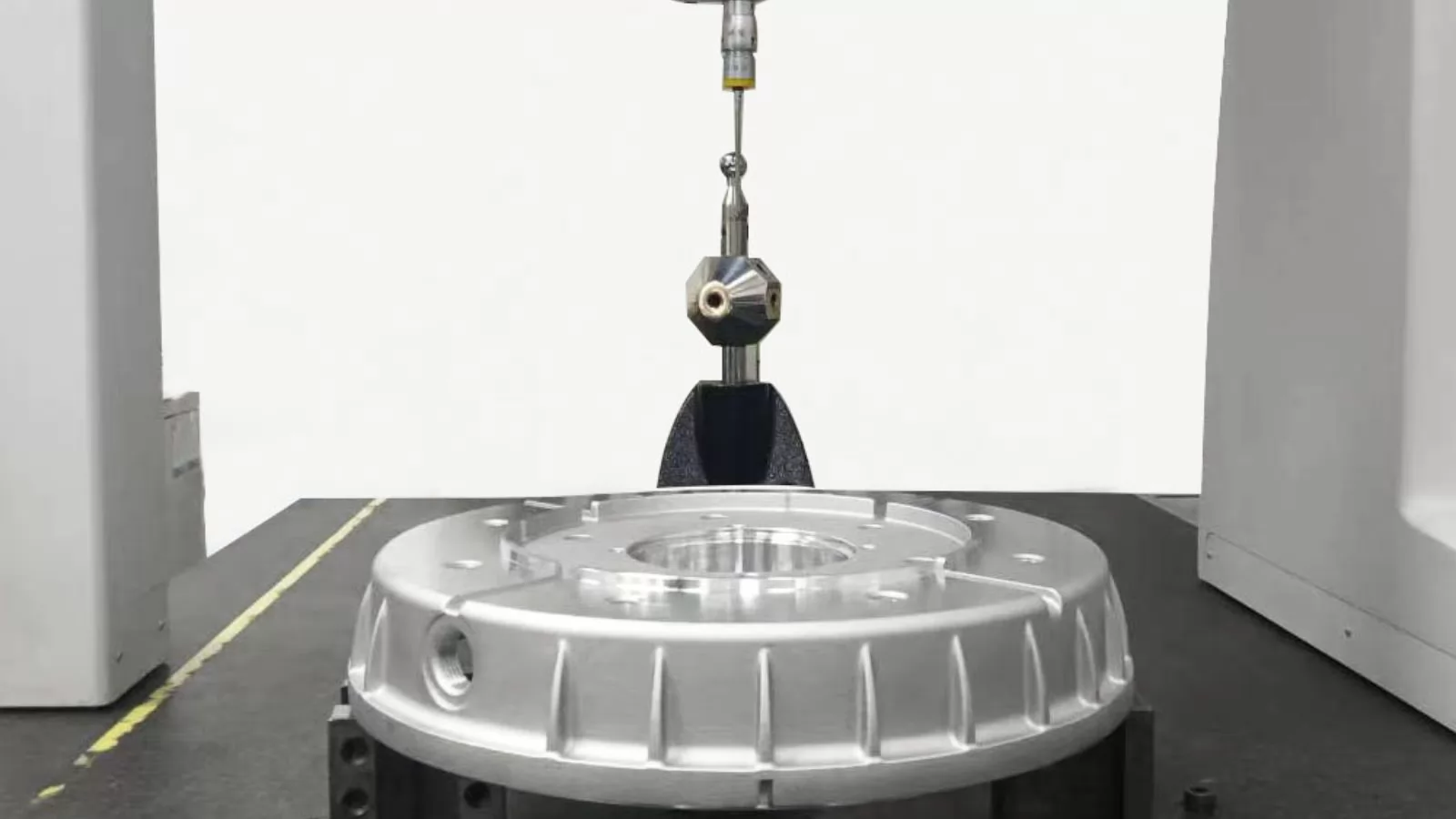
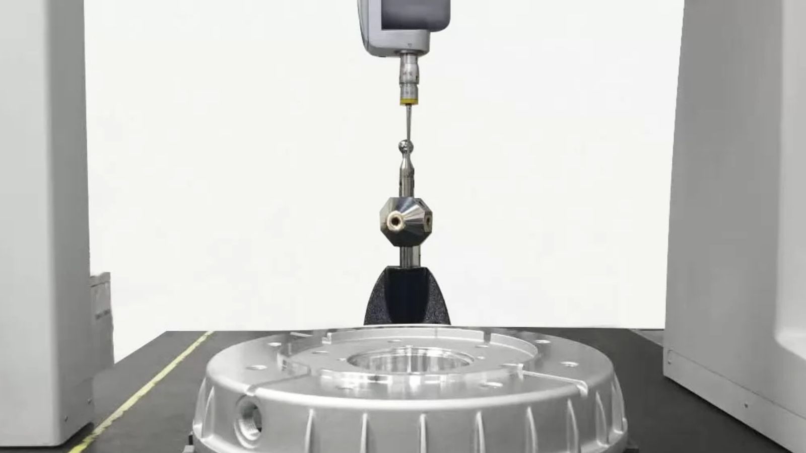
How Are Die Cast Parts Inspected for Tolerance Compliance?
Defining tolerances is only half the equation. Verifying that production parts consistently meet those tolerances requires a structured inspection approach — one that combines the right measurement tools with systematic process monitoring throughout the production run, not just at the end of it.
Dimensional Measurement Tools
The choice of measurement tool depends on the feature being inspected, the tolerance being verified, and the volume of parts being checked. Common tools used in die casting inspection include:
| Tool | Best For | Typical Accuracy |
|---|---|---|
| Calipers / Micrometers | Linear dimensions, wall thickness, hole diameters | ±0.01 mm |
| Coordinate Measuring Machine (CMM) | Complex 3D geometry, GD&T verification, multi-feature reports | ±0.002–0.005 mm |
| Optical Comparator | Profile and form inspection for small or detailed features | ±0.005 mm |
| 3D Laser Scanning | Full-surface deviation mapping vs. CAD model | ±0.02–0.05 mm |
| Go / No-Go Gauges | High-volume pass/fail checks on critical features | Feature-specific |
For first-article inspection, CMM measurement against a detailed inspection plan is standard practice. For in-process monitoring during high-volume runs, a combination of go/no-go gauges and periodic CMM sampling provides practical coverage without slowing production.
Non-Destructive Testing Methods
Dimensional inspection confirms that external geometry is within tolerance — but it cannot reveal internal defects that may affect structural integrity or long-term performance. Non-destructive testing (NDT) methods address this gap without damaging the part.
X-ray and CT scanning are the most widely used NDT methods in die casting. X-ray inspection detects internal porosity, voids, and inclusions in two dimensions. Industrial CT scanning goes further, producing a full 3D map of the part's interior — including wall thickness variation, internal channel geometry, and subsurface defects — and comparing it directly to the CAD model.
CT scanning is particularly valuable during tooling validation, where confirming that internal features meet dimensional requirements before committing to high-volume production can prevent costly tooling rework later.
First-Article and In-Process Inspection
A well-structured inspection program distinguishes between two distinct stages of production:
First-article inspection (FAI) is conducted on the initial parts produced from a new or modified die. It verifies that the tooling is producing parts within specification across all critical dimensions before full production begins. Any deviations identified at this stage can be corrected through die adjustment at relatively low cost.
In-process inspection monitors dimensional performance across the production run. Sample parts are measured at defined intervals — typically every few hundred shots — and results are plotted on control charts. This allows operators to detect gradual drift from die wear or process variation and make corrections before parts go out of tolerance.
Statistical Process Control in Practice
Statistical Process Control (SPC) transforms inspection data into actionable process intelligence. Rather than simply sorting good parts from bad, SPC tracks whether the process itself is stable and centered within tolerance limits.
Two key metrics used in SPC for die casting are Cp (process capability, measuring spread relative to tolerance width) and Cpk (process capability index, accounting for both spread and centering). A Cpk value of 1.33 or higher is typically required by automotive and aerospace customers as evidence of a capable, well-controlled process.
In practical terms: a Cpk of 1.33 means the process mean is at least four standard deviations away from the nearest tolerance limit — leaving meaningful margin for natural process variation without producing out-of-tolerance parts.
Choosing the Right Tolerance Level for Your Project
Specifying tolerances is one of the most consequential decisions made during die casting project development. Too loose, and parts may not assemble or function correctly. Too tight, and costs escalate unnecessarily through complex tooling, secondary machining, and elevated scrap rates. The goal is to find the level that genuinely serves the application — no tighter, no looser.
Start with Function, Not Habit
The most common tolerance mistake in die casting projects is carrying over precision specifications from machined-part drawings without reassessing whether that precision is actually needed in a cast component. Before assigning any tolerance value, it is worth asking: what happens if this dimension varies by ±0.10 mm? If the answer is "nothing significant," a standard tolerance is appropriate. If the answer is "the seal leaks" or "the shaft binds," a tighter limit is warranted.
A useful rule of thumb: apply precision tolerances only to features that directly affect fit, function, or safety. Allow standard tolerances on everything else. On a typical aluminum die cast housing, this might mean precision control on two or three critical interfaces — and standard tolerances across the remaining thirty features.
Consider the Full Production Cost
Tighter tolerances do not just affect tooling cost — they have a ripple effect across the entire production process. The table below illustrates how tolerance level choices translate into real cost implications:
| Decision | Standard Tolerance | Precision Tolerance |
|---|---|---|
| Tooling investment | Lower — standard machining accuracy | Higher — tighter cavity machining required |
| Scrap and rework rate | Lower — wider acceptance window | Higher — more parts may fall outside limits |
| Inspection complexity | Simpler — gauge and caliper checks often sufficient | Greater — CMM or optical verification typically required |
| Secondary machining | Rarely needed | Often required for critical features |
| Die maintenance frequency | Standard intervals | More frequent — less wear margin available |
Understanding these cost relationships allows designers and procurement teams to make informed trade-offs rather than defaulting to the tightest tolerances available.
Align Early with Your Manufacturer
Tolerance decisions made in isolation — without input from the die caster — frequently result in specifications that are either unnecessarily costly to achieve or practically unachievable with the intended process. Engaging the manufacturer during the design phase allows tolerance requirements to be validated against actual process capability before tooling is committed.
A capable die casting partner will review your drawing, identify which tolerances are within standard capability, which require precision-grade tooling or secondary operations, and which may need to be renegotiated based on part geometry. This conversation is far less expensive before the die is cut than after the first article fails inspection.
FAQ
Q: What is the minimum tolerance achievable in aluminum die casting?
Under precision production conditions with high-quality tooling, aluminum die casting can achieve linear tolerances as tight as ±0.05 mm (±0.002 in) without secondary machining. For critical features such as bearing bores or precision locating surfaces, secondary CNC machining can bring this down to ±0.01–0.02 mm. The achievable minimum depends on feature size, part geometry, and alloy selection.
Q: How do NADCA tolerance grades work?
NADCA publishes two tolerance tiers for die casting: Standard and Precision. Standard tolerances represent what is achievable under normal production conditions and are the most economical. Precision tolerances require tighter tooling, closer process control, and sometimes secondary operations. Both tiers provide separate values for different alloys — aluminum, zinc, and magnesium — and scale with part dimension, meaning larger features are assigned wider allowable variation. Full NADCA product standards are available through the NADCA website.
Q: What is the difference between NADCA and ISO 8062-3 tolerance standards?
NADCA is a North American industry standard focused specifically on die casting, with detailed tables for aluminum, zinc, and magnesium alloys. ISO 8062-3 is an international standard covering all casting processes, using a graded DCTG system (DCTG 1–16) that provides a universal reference for global supply chains. High-pressure die castings typically fall in the DCTG 4–6 range under ISO 8062-3. Both standards are widely used and often referenced together in engineering drawings.
Q: When should secondary machining be used to meet tighter tolerances?
Secondary machining is appropriate when specific features require tolerances tighter than ±0.05 mm, or when geometric requirements — such as concentricity, perpendicularity, or surface finish — cannot be reliably achieved through casting alone. Common candidates include bearing seats, threaded bores, precision locating features, and sealing faces. The preferred approach is to cast the part near net shape and machine only the features that require it, preserving the cost and speed advantages of die casting for the rest of the geometry.
Q: How does pressure die casting compare to sand casting in dimensional accuracy?
The difference is significant. High-pressure die casting typically achieves linear tolerances in the ±0.05–0.13 mm range, corresponding to ISO DCTG grades 4–6. Sand casting, by contrast, generally achieves ±0.50–1.50 mm, placing it in the DCTG 11–13 range. Sand cast parts almost always require secondary machining to meet functional dimensional requirements, whereas pressure die cast parts frequently meet specifications directly from the die.
Q: Can die casting tolerances be maintained consistently across large production runs?
Yes — provided the process is properly controlled and the tooling is regularly maintained. The primary risks to long-run consistency are die wear, gradual process drift, and alloy composition variation between material batches. Manufacturers using Statistical Process Control (SPC) with regular dimensional auditing can detect and correct these trends before they affect part quality. A well-maintained die casting process can hold tolerances consistently across hundreds of thousands of parts.
Q: Does part size affect what tolerances are achievable?
Yes, directly. Both NADCA and ISO 8062-3 scale tolerance allowances with part dimension — larger features are assigned wider permissible variation. This reflects the physical reality that larger castings accumulate more shrinkage, experience greater thermal gradients during cooling, and are more susceptible to warping. For large aluminum die castings, it is common to apply tighter tolerances locally to critical interface features while accepting wider variation across the overall envelope of the part.
0
Comments
Leave a Comment
Your email address will not be published. Required fields are marked *
Name can't be empty
Email error!
Message can't be empty
😍
😜
😳
😌
😄
😘
😝
😒
😃
😚
😚
😛
😟
😧
😀
😉
😓
😱
😤
😣
😂
😥
😩
😠
😢
😭
😰
😨
😡
😆
😪
😅
😐
😇
😋
😴
👿
😕
😏
😷
😵
😟
😮
😯
😑
👧
👴
😧
😬
😾
👶
👱
👵
👸
🙀
👺
👦
👩
👨
😽
😿
🙈
💩
💥
💤
😼
😹
🙉
🔥
✨
💦
👎
✌
👆
👈
💪
💹
👍
👊
💴
💶
💷
💸
👉
💵
🙏
🌎
🏧
👏
💳
👇
💑
🙆
🙅
💁
👫
👭
🙎
🙇
👑
👔
Submit Comment
Most Popular
-
 Jan 30, 2026Aluminum Die Casting Cost Breakdown: From Material to Machining
 -
 Oct 22, 2025Top 10 Aluminium Die Casting Manufacturers and Suppliers in the World
 -
 Nov 26, 2025Top 10 Aluminium Low Pressure Die Casting Manufacturers in the World 2026
 -
 Nov 21, 2025Top 10 Precision Aluminium Investment Casting Factories and Manufacturers in China


Laster Blogs
-
 Mar 27, 2026Die Casting Tolerances: Standards, Types, and What to Expect from Aluminum
 -
 Mar 26, 2026Magnesium vs Aluminum: Weight, Strength, Price & Alloy Comparison
 -
 Mar 25, 2026Die Casting Porosity Guide: Causes, Types, Standards and How to Reduce It
 -
Mar 24, 2026Top 10 Precision Aluminium Investment Casting Factories and Manufacturers in China


Send RFQ Today
Name can't be empty
Email error!
Send Your Message
Note: If you are looking for a job, please send an email to it2@innovaw.com