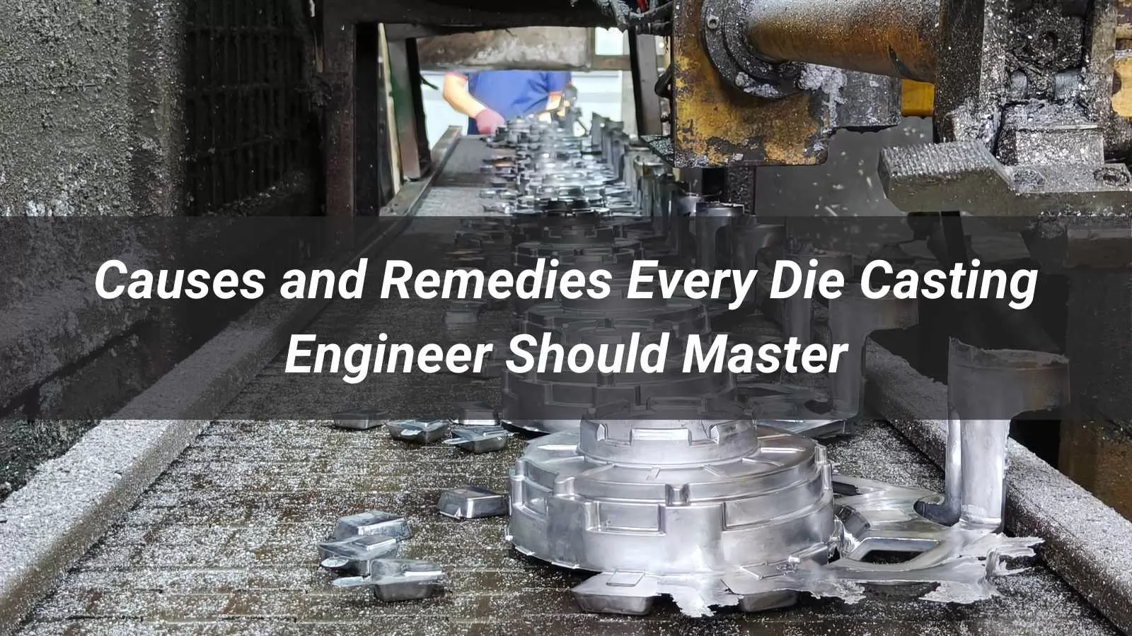
Know Your Casting Defects? 10 Causes and Remedies Every Die Casting Engineer Should Master
In die casting production, casting defects are inevitable — but uncontrolled defects are not. Across industries from automotive to consumer electronics, porosity, cold shut, flash, and cracking remain among the leading causes of scrap, rework, and production delays. Yet in most cases, the defect itself is not the problem. The real issue is misidentifying its cause.
This guide addresses the core question that every die casting operation faces: why do defects occur, and what actually fixes them? As global demand for lightweight aluminium and zinc die castings continues to grow — driven by EV component manufacturing, miniaturized electronics, and precision structural parts — the pressure to deliver consistent quality at higher volumes has never been greater. Understanding defect causes and remedies is no longer a troubleshooting skill reserved for senior engineers; it is a baseline competency for anyone involved in the casting process. This guide is written for:
- Die casting process engineers managing day-to-day production quality
- Tooling and die design engineers optimizing new or existing tooling
- Quality engineers responsible for defect analysis and rejection control
- Production managers looking to reduce scrap rates and improve yield
The ten defects covered in this guide represent the most common, costly, and misunderstood quality issues in die casting — each examined through the lens of causes, identification, and proven remedies. Read on to build a clearer, more systematic understanding of what drives casting defects and how to address them at the source.
Table of Contents
- What Is a Die Casting Defect?
- Classification of Die Casting Defects
- Defect #1 — Porosity
- Defect #2 — Cold Shut / Cold Flow
- Defect #3 — Shrinkage
- Defect #4 — Flash
- Defect #5 — Cracks
- Defect #6 — Flow Marks
- Defect #7 — Blisters
- Defect #8 — Soldering & Drag Marks
- Defect #9 — Misrun / Short Fill
- Defect #10 — Inclusions
- Defect Classification Summary Table
- What Does a Systematic Approach to Die Casting Defect Prevention Actually Look Like?
- Conclusion
What Is a Die Casting Defect?
A die casting defect refers to any irregularity in a finished casting that causes it to deviate from its intended design specifications — whether in appearance, internal integrity, or dimensional accuracy. These defects can arise at virtually any stage of the production cycle: from alloy selection and melt preparation, through injection and solidification, to ejection and post-processing.
In high pressure die casting (HPDC), molten metal is injected into a steel die at speeds typically ranging from 10 to 50 m/s and pressures exceeding 700 bar. This extreme environment makes the process highly efficient, but also highly sensitive — small variations in temperature, pressure, or die condition can trigger a cascade of quality issues.
Defects are not exclusive to one process. Whether working with aluminium die casting, zinc alloy die casting, gravity die casting, or even sand casting, each process carries its own characteristic defect profile. For example:
- High pressure die casting defects are often gas-related due to the turbulent fill pattern
- Aluminium gravity die casting defects tend toward shrinkage and misrun due to slower fill velocities
- Cast iron defects frequently involve graphite morphology issues and slag inclusions
Understanding and controlling casting defects is not merely a quality concern — it directly affects tooling life, scrap rate, downstream machining costs, and ultimately customer satisfaction. Industry references such as the Casting Defects Handbook (AFS) provide standardized frameworks for defect identification, root cause analysis, and corrective action across all major casting processes.
A defect that goes undetected before shipment can cost 10× more to address than one caught at the casting stage.
Classification of Die Casting Defects
Before examining individual defect types, it is essential to establish a clear classification framework. Die casting defects are commonly categorized along two axes: how they manifest (form-based) and where they originate (cause-based). This dual-axis approach is widely used in industrial quality systems and aligns with standards such as NADCA Product Specification Standards and ISO 8062.
1. Surface Defects
Surface defects are visible on the exterior of the casting and are typically identified through visual inspection or dye penetrant testing.
- Examples: Flow marks, blisters, soldering, drag marks, flash, cold shut lines, surface cracks
- Common in: High pressure die casting of aluminium and zinc alloys; also seen in aluminium gravity die casting
- Impact: Compromises aesthetics, interferes with coating, anodizing, or plating adhesion, and can affect secondary machining quality
- Identifying features: Often appear as discoloration, surface irregularities, raised or recessed lines, or excess material at parting lines
Surface defects are among the most commercially sensitive category — even structurally sound castings may be rejected if surface finish standards are not met.
2. Internal Defects
Internal defects are concealed within the casting body and cannot be detected by the naked eye. They represent the most structurally dangerous category of die casting defects.
- Examples: Gas porosity, shrinkage porosity, inclusions, cold shuts (deep), interlayers
- Detection Methods: X-ray radiography, industrial CT scanning, ultrasonic testing (UT), destructive cross-section analysis
- Impact: Reduces mechanical strength, compromises pressure tightness (critical for hydraulic or pneumatic components), and accelerates fatigue failure
- Identifying features: Round or irregular voids, layered separations, or foreign material embedded within the casting cross-section
In aluminium die casting, gas porosity is the most frequently reported internal defect, largely due to hydrogen solubility in molten aluminium and air entrapment during high-speed injection.
3. Dimensional & Structural Defects
Dimensional defects occur when the casting geometry or size deviates from design specifications, even if the material itself is sound.
- Examples: Warpage, deformation, short fill (misrun), flash-induced dimensional shift
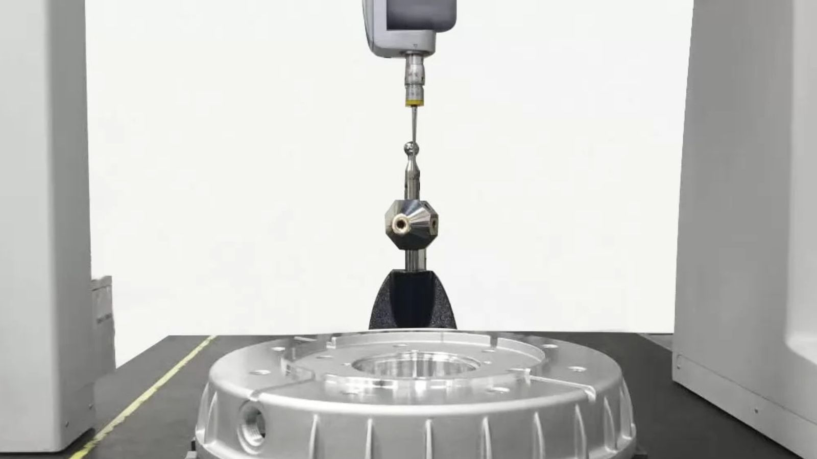
- Detection Methods: CMM (coordinate measuring machine), go/no-go gauges, 3D scanning, visual inspection
- Impact: Assembly fit failure, functional performance issues, increased rejection and rework rate
- Identifying features: Parts that fail gauge checks, exhibit visible warping, or show incomplete filling in thin-wall sections
Dimensional defects are particularly critical in automotive and aerospace applications where tight tolerances are mandatory.
4. Classification by Defect Origin
Understanding where a defect originates is equally important as knowing what it looks like. The table below maps each origin category to its typical defects — a foundational tool for root cause analysis and corrective action planning.
| Origin Category | Description | Typical Defects |
|---|---|---|
| Metallurgical | Alloy composition imbalance, melt contamination, hydrogen absorption, improper degassing | Gas porosity, shrinkage, inclusions, hot cracks, cold cracks |
| Process-related | Incorrect injection speed/pressure, fill temperature, holding time, venting performance | Cold shut, flow marks, short fill (misrun), blisters, shrinkage |
| Tooling / Die-related | Die design flaws, inadequate draft angles, worn inserts, poor venting/overflow system | Flash, soldering, drag marks, turtle cracks, interlayers |
| Machine-related | Insufficient clamping force, worn toggle mechanism, inconsistent shot control | Flash, dimensional deviation, blisters, short fill |
Practical Note: Many defects have multi-origin causes. Flash, for instance, can stem from insufficient clamping force (machine), excessive injection speed (process), or a worn parting surface (tooling) — which is why systematic diagnosis always outperforms single-factor troubleshooting.
Defect #1 — Porosity
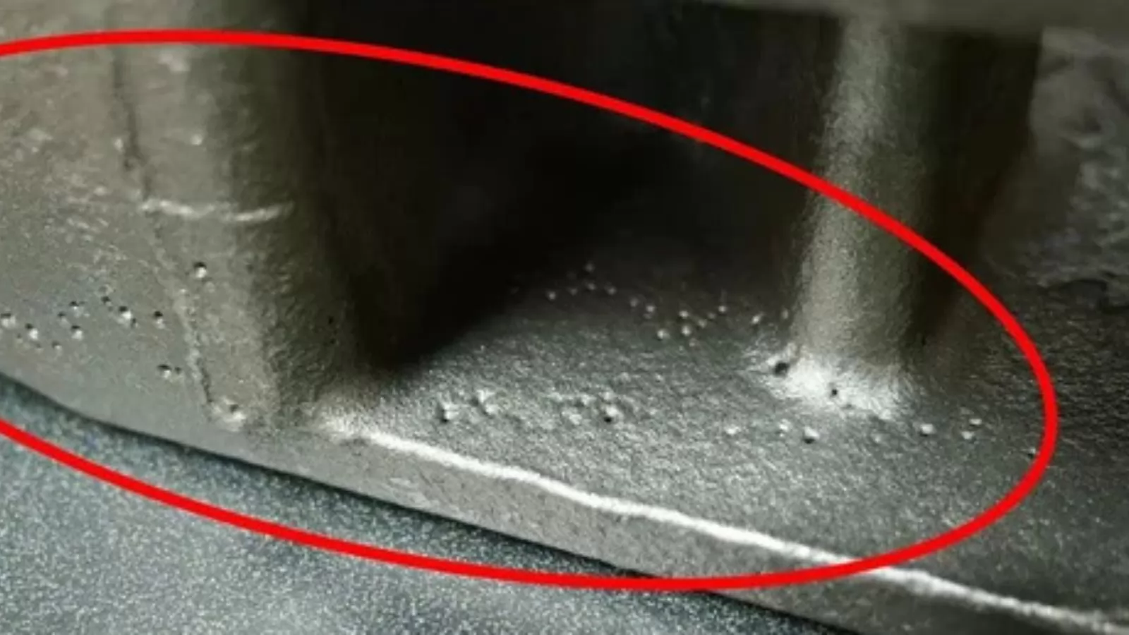
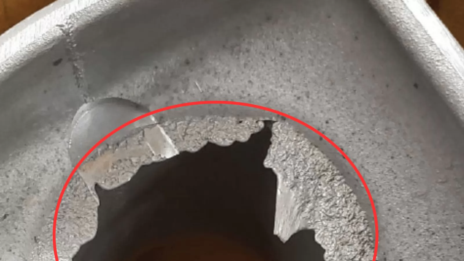
Porosity refers to the presence of voids or porous regions within or on the surface of a finished casting. It is one of the most prevalent internal defects in die casting and can significantly compromise mechanical strength, pressure tightness, and fatigue performance.
There are two distinct types:
- Gas Porosity: Round or oval voids with smooth, bright inner walls. Caused by trapped air during high-speed injection or hydrogen released from molten aluminium during cooling. Distribution tends to follow flow patterns rather than part geometry.
- Shrinkage Porosity: Irregular, rough-edged cavities concentrated in thick-wall sections or last-to-solidify areas. Caused by volumetric contraction without adequate feed metal compensation.
Root causes span three levels. At the metallurgical level: moisture-contaminated ingots, insufficient melt degassing, and high oxide content in recycled material all elevate risk. At the process level: turbulent cavity filling, excessive release agent use, and inadequate venting are primary drivers. At the tooling level: poorly positioned overflow wells and undersized venting channels prevent gas evacuation during fill.
Detection relies on X-ray radiography for routine inspection, industrial CT scanning for full 3D void mapping, and destructive cross-section analysis for root cause investigation. For pressure-critical components such as hydraulic housings or engine brackets, leak testing under pressurized air or fluid is a mandatory final step.
Key preventive measures:
- Ensure all ingots and tools are dry; perform rotary degassing of the melt before casting
- Optimize injection speed profile to minimize turbulent flow during cavity fill
- Use mold flow simulation to position venting channels and overflow wells at gas trap zones
- For demanding applications, consider vacuum-assisted die casting (VADC) to evacuate the cavity before injection
Practical Note: In aluminium high pressure die casting, some level of gas porosity is nearly unavoidable. The goal is not elimination but control — keeping porosity within acceptance thresholds defined by standards such as ASTM E505 or customer-specific X-ray inspection criteria.
Defect #2 — Cold Shut / Cold Flow
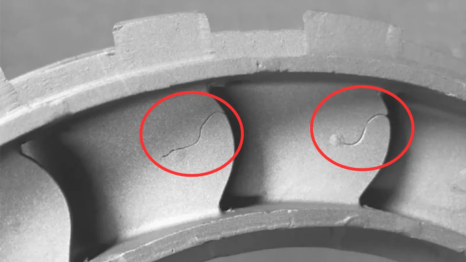
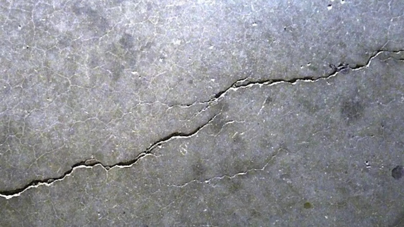
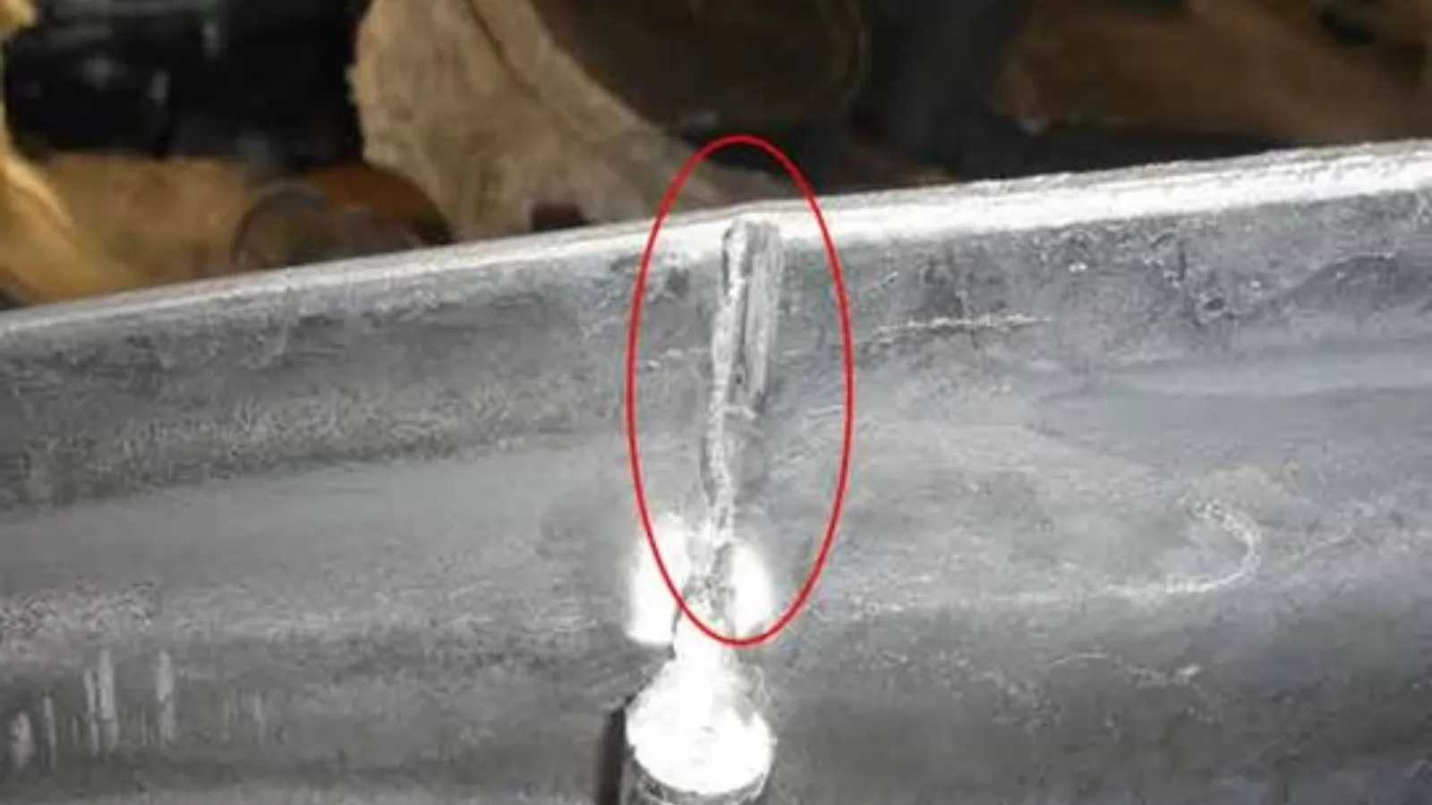
A cold shut occurs when two separate streams of molten metal meet inside the die cavity but fail to fuse completely due to premature surface solidification. The result is a visible linear seam on the casting surface — typically a narrow, depressed mark with smooth, rounded edges. In severe cases, the unfused junction becomes a structural weakness that can propagate under mechanical load.
Cold shut is closely related to cold flow, but the two are not identical. Cold flow produces surface streaks without a complete bond failure, whereas cold shut represents an actual unfused metal interface. The distinction matters for both rejection criteria and corrective action selection.
The root causes fall into three main areas:
- Low fill temperature: Insufficient pouring or die temperature causes flow fronts to develop a solidified skin before they can merge
- Poor metal fluidity: High Fe content, low Si, or excessive oxide films on the melt prevent proper convergence of flow fronts
- Gating system design: Long flow distances, opposing flow fronts without planned merge zones, and insufficient injection speed all increase cold shut risk
Cold shut is particularly critical in automotive structural parts, hydraulic housings, and pressure-tight components. Even where structural failure is not immediate, the surface seam typically fails cosmetic or coating adhesion requirements.
Prevention centres on maintaining metal fluidity through the full fill cycle: increase pouring and die temperature, raise injection speed and pressure, shorten flow distance through gating redesign, and place overflow wells at convergence zones to flush cold metal out of the cavity. Mold flow simulation is highly effective at identifying cold shut risk zones before tooling is committed.
Practical Note: Cold shut is frequently misidentified as a crack during visual inspection. The key differentiator is edge morphology — cold shut edges are smooth and rounded, formed by solidified flow fronts, whereas crack edges are sharp and irregular, formed by mechanical fracture. Correct identification is essential before applying any corrective action.
Defect #3 — Shrinkage
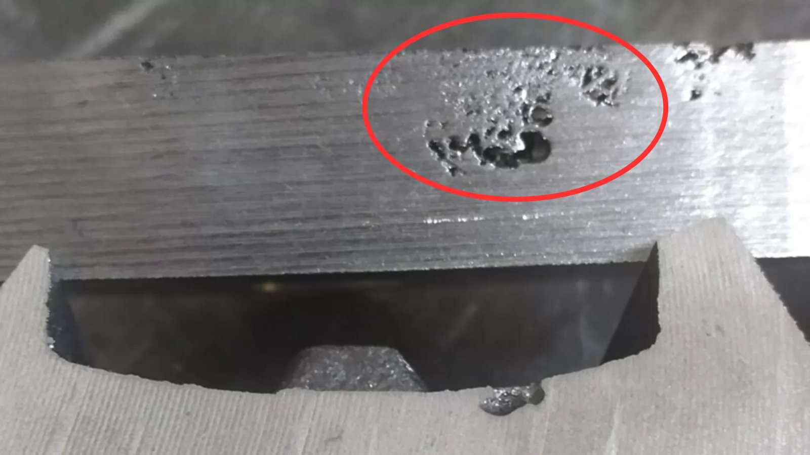
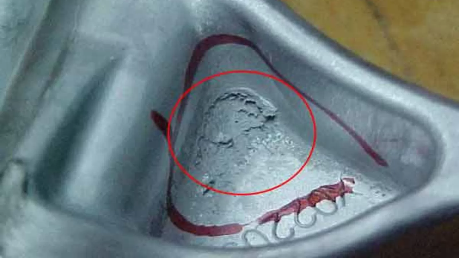
Shrinkage defects arise from the volumetric contraction that occurs as molten metal transitions from liquid to solid. When the feed metal supply is insufficient to compensate, voids or surface depressions form in the casting. Internally this manifests as shrinkage porosity — irregular, rough-walled cavities in last-to-solidify regions. On the exterior it appears as sink marks — concave depressions typically located above heavy bosses, thick ribs, or isolated geometric masses.
Wall thickness variation is the dominant geometric contributor. Thin walls solidify first and seal off adjacent thick sections from the feed metal supply; as the isolated mass continues to contract, a void or surface depression forms. This is why die casting design guidelines universally recommend:
- Uniform wall thickness wherever possible
- Gradual transitions between thin and thick sections
- Coring of unavoidable heavy sections to reduce isolated thermal mass
On the process side, the primary drivers are localized die overheating (caused by inadequate cooling channel placement near thick sections) and insufficient intensification pressure or holding time during solidification. Both prevent effective feed compensation before the gate freezes off.
Key corrective actions:
- Optimize die cooling circuit layout to achieve balanced thermal extraction across the cavity
- Increase intensification pressure and extend pressure-holding time
- Reposition or resize the ingate to keep the gate liquid until the casting has adequately solidified
- Use thermal simulation tools (MAGMASOFT, ProCAST) to predict hot spots before die fabrication
Practical Note: Shrinkage porosity and gas porosity frequently coexist and are often confused. A reliable differentiator is location — shrinkage porosity appears in geometrically predictable hot spots such as thick sections and isolated masses, while gas porosity distribution follows flow patterns and is less geometrically constrained.
Defect #4 — Flash
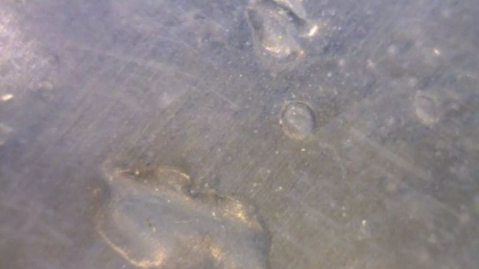
Flash is a thin fin or web of excess metal that forms outside the intended casting envelope — most commonly at the parting line, around ejector pins, or at die insert interfaces. It is one of the most immediately visible die casting defects and occurs across all pressure die casting processes. While flash does not inherently compromise internal integrity, it always demands secondary deflashing operations that add labour cost and cycle time.
The underlying causes divide into three categories:
- Machine condition: Insufficient clamping force, worn toggle mechanisms, or uneven platen parallelism allow die halves to separate slightly under injection pressure
- Tooling wear: Eroded parting surfaces, worn sliders or inserts, and foreign material preventing full die closure create direct leakage pathways
- Process parameters: Excessive injection speed or pressure generates cavity pressure that overcomes available clamping force, especially on worn tooling
The downstream impact extends beyond deflashing cost. Flash at critical mating surfaces causes dimensional inspection failures; on sealing faces or threaded interfaces, unremoved flash leads to assembly or functional failure in service. Repeated flash formation also accelerates parting surface wear — a progressive deterioration cycle that compounds with each production run.
Prevention requires both process discipline and scheduled tooling maintenance: verify clamping force calculations against projected cavity area and peak injection pressure; clean parting surfaces before every production run; reduce injection speed and pressure to the minimum effective level; and inspect parting surface flatness and insert wear as part of routine die maintenance.
Practical Note: Flash and short fill are directly in conflict — increasing injection pressure to cure a misrun may simultaneously introduce flash at a worn parting surface. Address tooling wear before adjusting process parameters; parameter changes on a worn die rarely produce a sustainable solution.
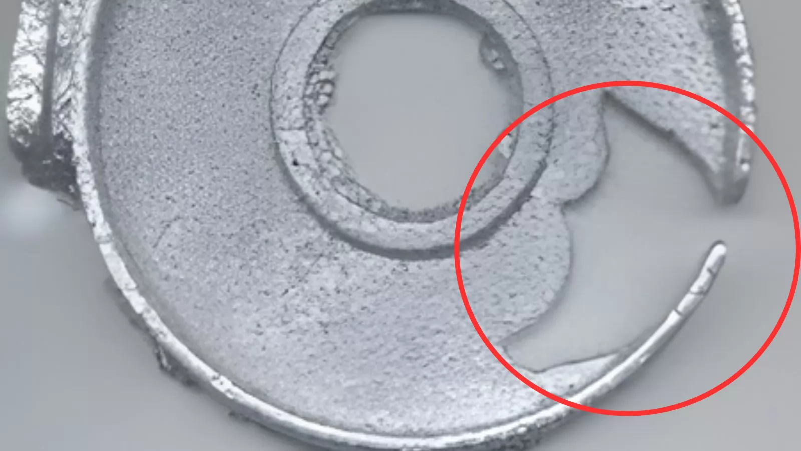
Defect #5 — Cracks
Cracks are fractures or fissures that form either during solidification or after ejection. They represent one of the most serious defect categories in die casting — structurally compromised parts are almost always rejected outright. Cracks divide into two types that are distinct in origin, appearance, and required corrective action:
| Feature | Hot Cracks | Cold Cracks |
|---|---|---|
| Formation Stage | During solidification (semi-solid state) | After solidification, during ejection or cooling |
| Crack Surface | Oxidized — dark or discoloured | Bright metallic lustre |
| Crack Path | Irregular, branching, intergranular | Linear, transgranular, follows stress concentrations |
| Typical Location | Near gates, heavy sections, last-to-solidify areas | Near ejector pins, sharp corners, thin-to-thick transitions |
Root causes span metallurgical, process, and design factors. Excess Fe in aluminium alloys reduces ductility and promotes hot tearing; incorrect Si, Zn, or Mg levels shift solidification behaviour and crack susceptibility. Ejection imbalance — uneven pin distribution, insufficient pin count, or premature ejection — is a frequent cold crack trigger. Non-uniform wall thickness and steep thermal gradients contribute to both types.
Corrective actions should be matched to the confirmed crack type:
- Hot cracks: Verify alloy chemistry, limit recycled material ratio, reduce pouring temperature, review casting geometry for abrupt section changes
- Cold cracks: Rebalance ejector pin layout, increase die temperature to reduce thermal gradient, improve draft angles to minimize ejection resistance
Before any corrective action, confirm crack type through visual inspection: check surface oxidation colour, trace the crack path, and apply dye penetrant testing (DPT) to reveal full crack extent and depth.
Practical Note: Hot and cold cracks require fundamentally different corrective strategies — addressing one may worsen the other. Increasing die temperature reduces cold crack risk but may aggravate hot tearing in susceptible alloys. Always confirm crack type before implementing process changes.
Defect #6 — Flow Marks
Flow marks are visible surface irregularities that appear as streaks, lines, or bands running in the direction of metal flow. Unlike cold shut, flow marks do not represent an unfused metal interface — they are purely surface phenomena with no structural bond failure. However, they are commercially significant: flow marks frequently cause rejection on cosmetic-grade castings and can interfere with coating, anodizing, and plating adhesion.
Flow marks form when the first wave of metal to enter the cavity partially solidifies against the die wall before subsequent metal fills behind it. The temperature differential between the early-solidified skin and the following metal stream creates a visible boundary on the surface. Contributing factors include:
- Low die temperature: Accelerates surface solidification of the leading metal flow, making boundary lines more pronounced
- Incorrect ingate design: An undersized or poorly positioned ingate causes metal to enter with excessive velocity, splashing and creating irregular flow patterns
- Insufficient injection pressure: Slow-moving metal loses temperature quickly, increasing the likelihood of visible flow boundaries
- Excess release agent: Thick release agent layers on the die surface disrupt smooth metal contact and leave residual surface marks
Flow marks are most commonly found on large, flat surfaces and thin-wall sections where metal travels the furthest from the ingate. They are a frequent issue in aluminium and zinc alloy die castings intended for decorative or visible applications.
Key corrective actions:
- Increase die temperature to slow surface solidification and allow flow fronts to merge smoothly
- Adjust ingate size and position to improve flow uniformity across the cavity
- Increase injection speed and pressure to maintain metal fluidity through the full fill
- Reduce release agent application quantity and ensure even, thin coverage
Practical Note: Flow marks and cold shut are visually similar but mechanically distinct. Flow marks have no depth and cannot be felt by running a fingernail across the surface; cold shut lines have a perceptible depression or step. When surface quality is critical, dye penetrant testing can confirm whether a visible line is cosmetic or structural.
Defect #7 — Blisters
Blisters are raised surface bubbles or bulges that appear on the casting exterior after ejection or during post-processing such as heat treatment or surface coating. They form when sub-surface gas — trapped during filling and compressed under injection pressure — expands outward once the casting is released from the die and the constraining pressure is removed. The result is a thin metal skin pushed away from the casting body, creating a hollow bubble that is fragile and easily ruptured.
Blisters are directly linked to gas entrapment but are distinct from internal porosity: the gas pocket is located immediately beneath the surface rather than deep within the casting. Key contributing factors include:
- Insufficient solidification time: Premature ejection before the casting skin has achieved adequate thickness allows sub-surface gas to expand and push the soft surface outward
- Overheated die temperature: Reduces casting skin strength, making the surface more susceptible to gas-driven deformation after ejection
- Excessive release agent or piston lubricant: Generates gas vapour within the cavity that becomes trapped beneath the casting surface during fill
- Poor venting performance: Trapped air compressed near the cavity surface has nowhere to escape and remains as a sub-surface gas pocket
Blisters may not be immediately visible after casting — they often appear or worsen during downstream operations. Heat treatment, powder coating, or even ambient temperature changes can trigger blister formation on parts that appeared acceptable at the time of casting. This makes blisters particularly problematic in production environments where surface finishing is performed off-site or at a later stage.
Key corrective actions:
- Extend solidification and pressure-holding time before ejection to allow adequate skin development
- Reduce die temperature in blister-prone zones to increase surface skin strength
- Improve cavity venting to allow sub-surface gas to escape rather than becoming trapped
- Reduce release agent and lubricant quantities; extend blow-off time after spraying
Practical Note: Blisters that only appear after heat treatment or coating are frequently misattributed to the downstream process rather than the casting operation. If blistering occurs consistently after a specific thermal cycle, the root cause is almost always pre-existing sub-surface gas — the heat treatment simply provides the energy for the gas to expand. Corrective action must target the casting process, not the finishing operation.
Defect #8 — Soldering & Drag Marks
Soldering and drag marks are two related but distinct ejection-phase defects that affect the casting surface quality and, over time, the condition of the die itself. Soldering occurs when molten metal bonds abnormally to the die cavity surface, leaving areas of excess or missing material on the casting after ejection. Drag marks appear as parallel scratches or gouges running in the die-opening direction, caused by the casting surface being abraded against the die wall during ejection.
Both defects share common root causes:
- Insufficient draft angles: Low or negative draft creates friction between casting and die wall during ejection, causing both surface damage and die wear
- Die surface condition: Low cavity hardness, poor surface finish, or surface damage creates adhesion points for molten metal
- Alloy composition: Insufficient Fe content in aluminium alloys increases the tendency to solder to steel die surfaces; Fe content is typically maintained at 0.8–1.0% specifically to reduce soldering risk
- Thermal factors: Overheated die temperature or excessively high pouring temperature accelerates metal-to-die adhesion, particularly at high-velocity ingate impingement zones
- Release agent quality: Poor or degraded release agent fails to maintain an effective separation barrier between metal and die surface
Beyond surface quality, both defects have significant tooling implications. Soldering causes progressive erosion of the die cavity surface; drag marks indicate repeated mechanical abrasion that accelerates die wear. Left unaddressed, either defect shortens die service life substantially and increases maintenance frequency and cost.
Key corrective actions:
- Review and increase draft angles on affected surfaces; ensure a minimum of 1°–3° depending on surface depth and alloy
- Improve die surface hardness (target HRC 45–48) and polish cavity surfaces to reduce adhesion tendency
- Redirect ingate flow to avoid direct impingement on cores or cavity walls
- Control pouring temperature and die temperature within recommended ranges
- Switch to a higher-quality release agent formulated for the specific alloy and die temperature range in use
Practical Note: Soldering tends to initiate at ingate impingement zones where metal velocity and temperature are highest. If soldering is localized to a specific area of the cavity, examining the ingate direction and velocity profile is often more productive than adjusting release agent parameters alone.
Defect #9 — Misrun / Short Fill
A misrun, also called short fill or incomplete fill, occurs when the molten metal fails to completely fill the die cavity before solidification, leaving portions of the casting with missing material. The unfilled areas typically appear at the furthest points from the ingate — thin sections, fine features, or deep recesses where metal arrives last and with the least remaining heat and pressure. Misrun is immediately identifiable by visual inspection and represents an outright rejection in all applications.
The defect results from a combination of insufficient metal fluidity and inadequate filling conditions. On the fluidity side, low pouring temperature, low die temperature, and poor alloy composition (high Fe, low Si) all reduce the metal's ability to flow into fine features before freezing. On the filling condition side, low injection pressure and speed fail to drive metal to the extremities of the cavity, while excessive back-pressure from trapped gas blocks the final fill stages.
Misrun is particularly common in:
- Thin-wall sections below 1.5 mm where metal loses heat rapidly
- Long, narrow ribs or fins distant from the ingate
- Complex geometries with multiple flow path splits that reduce metal velocity
- Parts with inadequate venting at end-of-fill locations, creating high back-pressure
Key corrective actions:
- Increase pouring temperature and die temperature to improve metal fluidity and extend fill time
- Increase injection speed and pressure to drive metal further into the cavity before solidification begins
- Add or reposition venting channels and overflow wells at short-fill locations to reduce back-pressure
- Review gating system design — increase runner and ingate cross-sectional area to reduce flow resistance
- Evaluate alloy selection for thin-wall or complex geometry parts where fluidity is critical
Practical Note: When misrun occurs consistently at the same location across multiple shots, it is almost always a venting or gating design issue rather than a parameter issue. Adding an overflow well at the short-fill zone is often the most direct and reliable solution, as it both reduces back-pressure and provides a thermal reservoir that keeps metal fluid longer at the end of fill.
Defect #10 — Inclusions
Inclusions are foreign particles or non-metallic materials embedded within the casting, either on its surface or in its interior. They appear as irregular-shaped cavities or pockets containing oxide films, slag, sand particles, graphite, or other contaminants. Surface inclusions can be identified visually, while internal inclusions require ultrasonic testing (UT) or X-ray inspection. In either location, inclusions create stress concentration points that reduce fatigue strength, machinability, and surface finish quality.
Inclusions enter the casting through several pathways:
- Melt contamination: Low-purity furnace charge, inadequate slag removal, or oxide films generated by overheating introduce non-metallic particles into the melt before casting
- Ladle and transfer contamination: Slag carry-over during metal ladling, dirty transfer tools, or refractory particles from furnace linings enter the melt stream
- Die cavity contamination: Residual metal fragments, release agent residue, or debris from previous shots remain in the cavity and become incorporated into the next casting
- Release agent composition: Release agents containing graphite can leave graphite inclusions in the casting surface if not properly mixed or if applied excessively
Inclusions are particularly damaging in machined surfaces — a subsurface inclusion revealed during machining creates a pit or void that may render the part unusable, especially on sealing faces, bearing surfaces, or hydraulic bores. In structural applications, oxide film inclusions are a known initiator of fatigue cracking under cyclic loading.
Key corrective actions:
- Use high-purity furnace charge and set a controlled ratio of new to recycled material
- Perform thorough slag removal and melt filtration before casting; keep ladles and transfer equipment clean
- Clean die cavity thoroughly between shots, particularly after any die maintenance or tool change
- If using graphite-containing release agents, ensure thorough mixing before application and minimize quantity used
- Implement incoming material inspection for alloy ingots to screen for contamination
Practical Note: Oxide film inclusions are among the most difficult inclusion types to eliminate in aluminium die casting because aluminium oxidizes rapidly on any exposed melt surface. Minimizing melt turbulence during transfer and ladling — using bottom-pour ladles where possible and avoiding excessive pouring height — is as important as melt treatment in controlling oxide inclusion levels.
Defect Classification Summary Table
The table below provides a consolidated reference across all ten defects covered in this guide — mapping each defect to its classification, primary cause category, detection method, and relative severity in a production context.
| # | Defect | Type | Primary Cause Category | Detection Method | Severity |
|---|---|---|---|---|---|
| 1 | Porosity | Internal | Process / Metallurgical | X-ray, CT scan, pressure test | High |
| 2 | Cold Shut / Cold Flow | Surface / Structural | Process / Gating Design | Visual, dye penetrant (DPT) | High |
| 3 | Shrinkage | Internal / Surface | Thermal / Process | X-ray, CT scan, visual (sink marks) | High |
| 4 | Flash | Dimensional / Surface | Machine / Tooling | Visual, dimensional inspection | Medium |
| 5 | Cracks | Structural | Metallurgical / Process / Design | Visual, dye penetrant (DPT) | High |
| 6 | Flow Marks | Surface | Process / Tooling | Visual | Low – Medium |
| 7 | Blisters | Surface | Process / Venting | Visual (post-ejection or post-finishing) | Medium |
| 8 | Soldering & Drag Marks | Surface | Tooling / Process | Visual | Medium |
| 9 | Misrun / Short Fill | Dimensional / Structural | Process / Gating Design | Visual | High |
| 10 | Inclusions | Internal / Surface | Metallurgical / Process | Visual, X-ray, UT | Medium – High |
What Does a Systematic Approach to Die Casting Defect Prevention Actually Look Like?
After reviewing ten of the most common die casting defects, a few fundamental questions are worth asking — not just when problems arise, but as part of every production cycle.
Q: Are you treating symptoms or root causes?
The most common mistake in die casting defect management is adjusting process parameters in response to visible symptoms without confirming the underlying cause. Increasing injection pressure to cure a misrun may introduce flash; raising die temperature to prevent cold shut may worsen shrinkage. Every corrective action should begin with a confirmed diagnosis — whether through visual identification, X-ray, dye penetrant testing, or cross-section analysis — before any parameter is changed.
Q: Is your tooling condition keeping pace with your quality expectations?
A significant proportion of recurring defects — flash, soldering, drag marks, misrun — trace back to progressive tooling wear that process adjustments can only partially compensate for. Regular die inspection, parting surface maintenance, and timely insert replacement are not optional overheads; they are prerequisites for consistent quality. If the same defect keeps returning after parameter correction, the die should be the next point of investigation.
Q: How well do you understand your metal before it enters the die?
Melt quality is the foundation on which every other process parameter depends. Porosity, inclusions, cold shut, and cracking are all significantly influenced by alloy chemistry, hydrogen content, oxide levels, and melt temperature — variables that are determined before the shot is fired. Implementing consistent melt treatment protocols, controlling recycled material ratios, and verifying alloy chemistry are upstream investments that reduce downstream defect rates across multiple defect types simultaneously.
Q: Are you using simulation before committing to tooling?
Mold flow simulation has become a standard tool in professional die casting operations for good reason. Porosity hot spots, cold shut risk zones, short-fill locations, and thermal imbalance can all be predicted and addressed during the design phase — at a fraction of the cost of modifying a finished die. For any new tooling project or significant design change, simulation should be considered a baseline requirement rather than an optional step.
Q: Is defect data being captured and acted upon systematically?
Isolated defect occurrences are production events; recurring patterns are process signals. Maintaining structured defect records — defect type, location, frequency, shift, material batch, machine — transforms quality data into actionable intelligence. Over time, this data reveals systemic issues that no single inspection pass would identify, and supports continuous improvement efforts with evidence rather than intuition.
Conclusion
Die casting defects are an inherent challenge of the process — but they are not uncontrollable. The ten defects covered in this guide represent the most frequently encountered quality issues across high pressure die casting, gravity die casting, and related aluminium and zinc alloy casting processes. Each has identifiable characteristics, traceable root causes, and proven corrective actions.
What separates consistently high-yield operations from those trapped in reactive firefighting is not the absence of defects, but the presence of a systematic approach: rigorous melt quality control, disciplined process parameter management, proactive tooling maintenance, and structured defect analysis. When these elements work together, defect rates become predictable, controllable, and — over time — continuously reducible.
Whether you are troubleshooting an existing production issue or designing a new casting from scratch, the principles in this guide provide a practical framework for making informed decisions at every stage — from alloy selection and die design through to final inspection and corrective action.
Looking to reduce defect rates in your die casting operation? The starting point is always the same: understand what you are seeing, trace it to where it comes from, and address the cause — not just the symptom.
0
Comments
Leave a Comment
Your email address will not be published. Required fields are marked *
Name can't be empty
Email error!
Message can't be empty
😍
😜
😳
😌
😄
😘
😝
😒
😃
😚
😚
😛
😟
😧
😀
😉
😓
😱
😤
😣
😂
😥
😩
😠
😢
😭
😰
😨
😡
😆
😪
😅
😐
😇
😋
😴
👿
😕
😏
😷
😵
😟
😮
😯
😑
👧
👴
😧
😬
😾
👶
👱
👵
👸
🙀
👺
👦
👩
👨
😽
😿
🙈
💩
💥
💤
😼
😹
🙉
🔥
✨
💦
👎
✌
👆
👈
💪
💹
👍
👊
💴
💶
💷
💸
👉
💵
🙏
🌎
🏧
👏
💳
👇
💑
🙆
🙅
💁
👫
👭
🙎
🙇
👑
👔
Submit Comment
Most Popular
-
 Nov 26, 2025Top 10 Aluminium Low Pressure Die Casting Manufacturers in the World 2026
 -
 Oct 22, 2025Top 10 Aluminium Die Casting Manufacturers and Suppliers in the World
 -
 Nov 26, 2025Top 10 Aluminium Low Pressure Die Casting Manufacturers in China
 -
 Dec 12, 2025Top 10 Aluminium Die Casting Manufacturers and Suppliers in China


Laster Blogs
-
 Mar 16, 2026Know Your Casting Defects? 10 Causes and Remedies Every Die Casting Engineer Should Master
 -
 Mar 13, 2026Top 10 Precision Aluminium Investment Casting Factories and Manufacturers in China
 -
 Mar 12, 2026Zinc vs Aluminum Die Casting: Which One Actually Fits Your Project?
 -
 Mar 11, 2026Die Casting Cost Guide: 7 Factors That Determine Mold Price


Send RFQ Today
Name can't be empty
Email error!
Send Your Message
Note: If you are looking for a job, please send an email to it2@innovaw.com